In my last post we had seen ........Reflex klystron oscillator .......but beside reflex,there is one more type of oscillator ........called ...magnetron.
A magnetron oscillator is used to generate high microwave power by using the interaction of stream of electrons with the magnetic field in a vacuum tube.Magnetron fall under the cross-field type tubes(M-Type).........in which we observe a unique property........i.e DC magnetic and DC electric field are perpendicular to each other.Following is a diagram of magnetron oscillator.............................................................
 |
| Magnetron Oscillator |
It consists of cylindrical cathode of finite length and radius 'a' at the center surrounded by a cylindrical anode of radius 'b'.The anode is a slow wave structure consisting of several re-entrant cavities(which is a tube with a plug at the end, usually a side path from the main waveguide - often to set up some type resonance in the microwave energy.)equi-spaced around the circumference and coupled together through the anode-cathode space by means of SLOTS.
Radial electric field is established by means by DC voltage Vo in between cathode and anode and DC magnetic flux denoted by Bo is mainted in positive Z direction by means of a permanent magnet or electromagnet.The elctrons emitted from the cathode travel towards the anode .But with the influence at the crossed fields E and H in the space between anode and cathode,it experiences this force called 'F'.
F= -eE-e(v*B)...........Lorentz Force which is the force on a point charge due to electromagnetic fields
where
e=electron charge
E=applied electric field
v=velocity of the electron.
B=applied magnetic field
Working:
The applied magnetic field Bo is constant and applied along the axis of the circular device illustrated. The power to the device is applied to the center cathode which is heated to supply energetic electrons which would, in the absence of the magnetic field, tend to move radially outward to the ring anode which surrounds it.
 | ||
| Pumping procedure |
Electrons are released at the center hot cathode by the process of thermionic emission and have an accelerating field which moves them outward toward the anode. The axial magnetic field exerts a magnetic force on these charges which is perpendicular to their initially radial motion, and they tend to be swept around the circle. In this way, work is done on the charges and therefore energy from the power supply is given to them. As these electrons sweep toward a point where there is excess negative charge, that charge tends to be pushed back around the cavity, imparting energy to the oscillation at the natural frequency of the cavity. This driven oscillation of the charges around the cavities leads to radiation of electromagnetic waves, the output of the magnetron.
Consider the Lorentz force equation : F= -eE-e(v*B)
- -eE ----------- force due to electric field
- -e(v*B) ---------------- force due to magnetic field
- Centrifugal force ------- m(v^2)/r
m(v^2)/r + eE = evB ......................where the electric field is in the radial direction.
Let
d/dt((r^2)*dΦ/dt) = (eB/m)*(r dr/dt)
= (ω/2) d/dt(r^2) ............since at grazing w= eB/m
OR
(r^2)*dΦ/dt = (ω/2)*(r^2) + k ....................integrating the above equation................(2)
At r = a
dΦ/dt=0
Therefore k= - (ω*(a^2))/2 .........................(3)
Since the electrons move in the direction perpendicular to magnetic field, the angular energy of electron is
dΦ/dt = (ω/2)*(1- (a/r)^2) ..........................(4)
The kinetic energy is given by by the electric field only
eV=m/2*[(dr/dt)^2+ (rdr/dt)^2] ........................(5)
At r = b
V=Vo(applied electric field) and
dr/dt= 0 for the electrons to just graze anode so that
(b*dΦ/dt)^2 = 2eVo/m ................................(6)
Substitute w= eBc/m in equation 6
Bc = [sqrt(8Vom/e)] / [ b (1- (a/b)^2]
where Bc= Hull cutoff magnetic field
Thus if Bo > Bc for a given DC voltage Vo, the electrons will not reach anode and hence no pumping action takes place and hence no microwave power will be generated.
For a given magnetic field Bo, the Hull cutoff voltage(Vc) is given as
Vc= [e(b^2)(Bo^2)(1- (a/b)^2)^2 ]/8m
Thus if Vo< Vc for a given Bo, the electrons will not reach anode.
Resonant modes:
The nature of field distribution in magnetron is such that alternating RF magnetic flux lines pass through cavities parallel to cathode axis and alternating RF fields are concentrated across the slot and fringe(spread out) to the interaction space between anode and cathode in the transverse direction.
For N resonant coupled cavities of the anode,there exist N resonant frequencies or modes
Since the anode which is a slow wave structure is closed on itself,the total phase shift around the internal periphery must be an integral multiple of (2π) for possible oscillations.
The phase shift between adjacent cavities is given by
Φn = 2πn/N
where n= 0 ,+- 1, + - 2, + - 3.................. + - N ---------> indicates nth mode of oscillation.
But n ≠ 0 because this would indicate zero RF fringing fields in the interaction region.
Average Drift Velocity :
Although electrons move in both Φ and r direction,they possess average drift velocity in Φ direction given by
vΦ = Er/Bz
When vΦ < Er/Bz the electron will be deflected towards the cathode.
Hartee Voltage :
Hartee voltage is an important specification of magnetron.Magnetrons are designed to operate in π mode where the phase difference between adjacent resonators is 180°. For strong interaction between the wave on anode structure and the electron beam, the phase velocity of wave should be nearly equal to drift velocity vΦ and the oscillations for π mode start at beam voltage
Voh = (2πf/N)*Bo*(
At the time high voltage is first applied to a magnetron,
 |
| Typical Thermal Drift Curves |
2. Temperature Coefficient
After the thermal drift period has expired and a stable operating frequency has been achieved, changes to ambient conditions which cause a corresponding change in the magnetron temperature will produce a change in the output frequency. In this content ambient changes include cooling air temperature or pressure in air cooled magnetrons; mounting plate temperature in heat sink cooled magnetrons; and flow rate or temperature in liquid cooled magnetrons.
The change in magnetron output frequency for each degree change in body temperature, as measured at a specified point on the
outside surface of the magnetron body, is defined as the Temperature Coefficient for the magnetron and is usually expressed inMHz/oC. For most magnetrons the temperature coefficient is a negative (frequency decreases as temperature increases) and is essentially constant over the operating range of the magnetron.
When estimating magnetron frequency change due to temperature coefficient, keep in mind that the temperature coefficient relates magnetron frequency to body temperature and there is not necessarily a 1:1 relation between body temperature and, for example,ambient air temperature. In addition, for airborne systems, the cooling effect of lower air temperature at altitude may offset by a
corresponding reduction in air density.
3.Pushing Figure
The pushing figure of a magnetron is defined as the change in magnetron frequency due to a change in the peak cathode current.Referring back to the earlier theory discussion, we noted that the resonant frequency of a vane resonator is determined by its mechanical dimensions plus the reactive effect of any perturbation. The presence of electrons in the vicinity of the vane tips affects the equivalent capacitance of the resonator by an amount proportional to the density of the electrons and,
since electron density is similarly related to peak pulse current, changes in pulse current level will produce changes in output frequency. The pushing figure expressed in MHz/Amp is represented by the slope of a frequency vs. peak current curve plotted for a particular magnetron type
From the curve of following figure , it can be seen that the slope is not a constant over the full range of operating current. It is therefore meaningless to talk about a specific value for the pushing figure unless one also specifies the range of peak current over which it applies.
It should be noted that since power output is proportional to peak current in a magnetron, the pushing figure at peak current levels
well below the normal operating point of the magnetron are usually unimportant because the power output at these current levels is low.
 |
| Typical Magnetron Pushing Curve |
The primary importance of a low pushing figure near the magnetron operating point is that the pushing figure will determine intrapulse FM, and thereby will affect the spectral quality of the transmitting pulse.
The Pulling Figure is defined as the maximum change in output frequency that results when an external, fixed amplitude mismatch, located in the output waveguide, is moved through a distance of one half wavelength relative to the magnetron. Stated somewhat less formally, the pulling figure is a measure of a magnetron's ability to maintain a constant output frequency against changes in load mismatch.
During the design of a magnetron, the degree to which the output
waveguide is electrically coupled to the internal resonator structure is selected to optimize certain performance parameters. Strong coupling increases output power and efficiency but also increases time jitter and sensitivity to changes to load mismatch. Generally, the coupling is chosen to obtain the best compromise between efficiency and stability.
Depending upon the phase relation between incident and reflected power at the output port of a magnetron, reflected power will appear as a reactance across the coupling transformer and effectively change the degree of coupling. Therefore, using a fixed mismatch and varying its distance from the magnetron output port will cause the magnetron frequency to shift and the output power to vary concurrently.
To standardize the measurement values, pulling figure is normally measured using a fixed 1.5:1 VSWR; however, in very high power magnetrons a 1.3 : 1 VSWR is often used. When referring to the pulling figure of a magnetron one should always indicate the VSWR value used in the measurement.
Applications :
- Radar - RAdio Detection And Ranging.
- Heating
- Lighting
Health Hazards :
Among more speculative hazards, at least one in particular is well known and documented. As the lensof the eye has no cooling blood flow, it is particularly prone to overheating when exposed to microwave radiation. This heating can in turn lead to a higher incidence of cataracts in later life.A microwave oven with a warped door or poor microwave sealing can be hazardous.
There is also a considerable electrical hazard around magnetrons, as they require a high voltage power supply.
Some magnetrons have beryllium, oxide (beryllia) ceramic insulators, which are dangerous if crushed and inhaled, or otherwise ingested. Single or chronic exposure can lead to berylliosis, an incurable lung condition. In addition, beryllia is listed as a confirmed human carcinogen; therefore, broken ceramic insulators or magnetrons should not be directly handled.
Grindell Mathews ( who invented death ray ) described losing the sight in one eye while testing his "Death Ray" in the 1920's which lends credence to the theory that it was based on a primitive magnetron albeit based on trial and error rather than the scientific method.
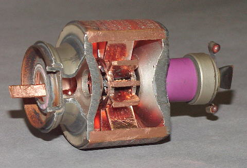
Above is a real life picture of practical magnetron with section removed to exhibit the cavities. The cathode in the center is not visible. The waveguide emitting microwaves is at the left. The magnet producing a field parallel to the long axis of the device is not shown.

Above is another picture of a practical magnetron with a different section removed. Central cathode is visible; antenna conducting microwaves at the top; magnet is not shown.
Thus we see that magnetron are useful as microwave tubes for delivering a power output upto 40KW with DC voltage of 50KV at 10GHz.The average power we obtain from magnetron is of the order 800 KW with an efficiency ranging from 40 to 70%
No comments:
Post a Comment